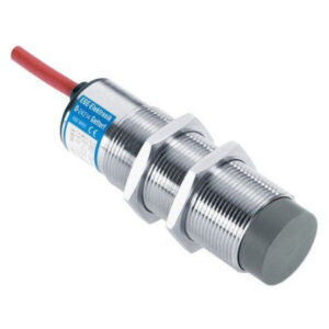
The basic operation of a non-contact speed switch is as described below. A suitable model as per application requirement is to be selected with the help of ordering information table.
Principle Of Operation
The speed / motion of rotating / moving object is sensed by a non- contact inductive type sensor. The sensor probe is installed with its sensing face in close vicinity of rotating object. The metallic pieces (flags) with specified dimensions are to be mounted on the rotating object. When these flags pass across the face of the probe, the frontally radiated electromagnetic field of the probe is damped which is converted to a corresponding output pulse. The pulse can also be generated by any other types of probes. These pulses are led to the monitoring unit via a separate interconnecting cable. The sensor probe can be mounted up to a maximum distance of 100 meters from the monitoring unit. The interconnecting cable should be of minimum 0.5sq. mm.size. These pulses are digital in nature and circuit is designed to work in electrically noisy area. An LED provided on rear side of a probe gives visual indication for sensing of the flag. In case of sensors other than inductive type, the pulses generated can be connected as specified for the individual sensor. The units are designed by using new advance micro controller based circuit. All operating features e.g.time delay, speed comparison, speed display, output relay operation are controlled precisely by the micro controller. Some parameters, related to design /operationof a speed switch, are as explained below.
Relay Logic
Different options of relay operation logic are available. For monitoring under speed it is recommended to have the relay energised at healthy speed (fail safe logic) and to drop out in case the speed drops. However, reverse or different operational logic can
be provided on request.
Speed Setting
The desired speed value can be set by means of potentiometer / keypad / trim pot. The potentiometer type units have a calibrated dial in 1:10 ratio.
Display
a) Dot LED for supply ON / Relay ON b) Speed Pulse c) Digital seven segment LED display up to 6 digit for speed.
Initial By-Pass Time Delay (ITD)
The monitoring under speed conditions it is essential to have a by-pass arrangement during starting of the machine. The output relay of the speed monitor is 'OFF' during starting / under speed condition and is 'ON' (energised) during healthy running speed. Hence it is essential to bypass (override) the relay contacts whilst starting. This can be achieved by using either an external timer unit, by programming through PLC or by using a built in by-pass time delay (ITD). With the built in ITD features the output relay switches 'ON' with 'Supply ON' condition and remains ON till the set time delay. If the equipment speed reaches its normal healthy speed during this time then the relay continuous to remain ON. The relay drops out if the speed has not reached the set value or when the speed drops below set value during run.
Nuisance Tripping Time Delay (NTD)
During run, the equipment may lose its speed momentarily due to various reasons. To avoid unnecessary tripping due to this, a built in time delay is provided. The output relay will drop out after the preset time delay after the speed has dropped below the set value. If the equipment speed recovers during this, then the relay continues to remain ON.
Hysteresis
The output relay has an inherent operating hysteresis characteristic (differential between relay ON/OFF) as given in Fig. 1. All standard models are provided with about 5% hysteresis value.


